ISSN: 0970-938X (Print) | 0976-1683 (Electronic)
Biomedical Research
An International Journal of Medical Sciences
Research Article - Biomedical Research (2017) Volume 28, Issue 6
An algorithm to improve the performance of medical signal filter with implementation using arm processor
1Department of Electronics and Communication Engineering, Sri Sairam Institute Of Technology, Anna University, Chennai, India
2Department of Computer Science and Engineering, Sri Sairam Institute Of Technology, Anna University, Chennai, India
3Department of Electronics, Madras Institute of Technology, Chennai, India
- *Corresponding Author:
- Saravanan Padmanaban
Department of Electronics and Communication Engineering
Sri Sairam Institute of Technology
Anna University, India
Accepted on October 17, 2016
Medical signals ruined with noise like electromagnetic interference and other sources must either to be filtered or eliminated, filtering is an important issue for design thought of real time health care and other process. This work presents a better Digital filter which can be implemented easily and has around 50% less power and area improvement. Usually, digital- filters were realized with dedicated Digital Signal Processors or FPGAs. Complexity, power consumption is more in this implementation as these methods need more computations especially multiplication. For better performance the multiplications is to be minimized, but ARM based processors like Cortex M4 consists command sets and hardware structure that can effectively run this nature of the calculations. The Aim of this paper is handling the signal processing activities on an ARM Cortex M4 in its place of employing another difficult Digital Signal Processor has the understandable benefit that an additional processor is not essential. This leads to low cost, minimum board space, less power expenditure, minimum outer bus passage and lower interfacing expenses. Everything can be united into a single build process and binary and no need to do repair on many processors from various vendors. Keeping everything on one processor simplifies the structure, cost of construction and selection of ARM as the processor is a clear one. As we have complete help from all the assets on the back of ARM, including forums, libraries, development tools, and we may employ a hardware structure that has turned into a customary in the Embedded Systems society which results in optimized performance in the realized Digital filter.
Keywords
Digital- filter design, Signal processing, ARM processor, Power reduction, Delay reduction, FIR filter.
Introduction
The source of digital signal filtering techniques can be traced back to the seventeenth century after the finite difference recent arithmetical power is given to us, the ability to manipulate the terrific amount of data in real time. Digital filtering is useful in a range of applications like speech recognition, medical image processing, etc. The FIR filters are the fundamental component of several digital signal processing algorithms. The hardware complexity leads to the significant amount of power dissipation. The thickness and space of integrated circuit essentials are improved exponentially for a period of many years, following Moore's Law. Though it is widely agreed that this development trend may not continue, it cannot be estimated precisely how thick and quick, integrated circuits can be made by this time. Operational devices are established, also fabricated using a MOSFET device with the channel length of 6.3 nanometers. The usual semiconductor resources, and devices were constructed which use carbon tubes as MOSFET gates, providing a channel length of about one nanometer. The compactness and arithmetic power of integrated circuits are restricted primarily by power concern.
Due to the volatile development in multimedia applications, the need of minimum-power and good-performance digital Signal Processing devices is higher than ever [1]. The Earlier Synchronous multipliers lead to complexity. The complexity reduction of FIR filter realization is also important as less computational complexity leads to optimized performance as well as less-power design. This reduced complexity is achieved with asynchronous multiplier [2]. Filter realized with hardware efficiency was proposed [3]. All the available energy should be used by reducing the leaked energy to get optimized the sub threshold proposal which reduces leaking power stated by [4]. The calculation reduction techniques in digital filters that minimize repeated calculations are planned. This method uses numeric optimization based on the reserved gene [5]. The architectural plan technique for realizing a single rate and multi rate improved-speed finite impulse response filter is discussed [6]. The first order sigma-delta is simple with the minimum area and the consumption of power reduces surprisingly. Unlike upper order structures, the first order sigma-delta is not susceptible to capacitor variance. Therefore, small capacitors can be used, which saves power.
The conventional delta-sigma modulator requires analog comparators, accurate integrators which results in design complexity. An alternate voltage controlled oscillator based modulator is proposed [7]. When the sampling rate is increased, and it makes decimation costlier in the digital domain an alternate method which is focusing on the efficient pipelined reduction of partial product was stated [8]. The usage of Optimal FIR Filter for detection of unknown inputs and in radio receiver has been stated [9,10]. The architectural modification leads to improvement in performance [11]. The different multiplier based digital filters are compared by Saravanan et al. [12] in the continuation of these improvements in digital filter we aims for a method with ARM processor as material which will provide optimum performance.
Implementation of Proposed Method
Digital-Filters are typically Finite Impulse Response (FIR) or Infinite Impulse Response (IIR). IIR filters utilize response for reprocessing the excitation, ending into delayed (i.e. unlimited) reaction to an input. FIR filters are steady, but have many calculation expenditures and lesser frequency accuracy than IIR filters. These IIR filters experience angular deformation, where excitations of various frequencies, moves through the filter at various rates (like signal dispersal). FIR filters typically are planned exclusively of angular deformation. IIR filters too contain equally "poles" and "zeros" but FIR Filters has simply Zeros [13]. Digital-filters regularly act on a large rate stream of data. They depend on the time decisive constraints, likely to be arithmetically concentrated and create intense use of multiply-combine calculations. ARM Cortex M4 processor have an extremely superior set of multiply-combine commands that can execute more than one integer multiply-combine operation in one clock period (e.g. SMLAD), which leads them to perform better in digital signal processing.
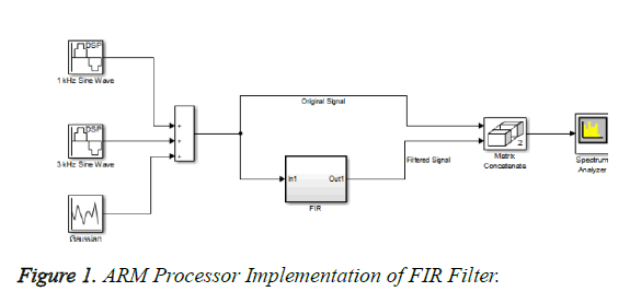
A digital filter is implemented easily by using MicroModeler DSP, which provides a browser-based, self-contained filter design environment. The Filter is dragged to the application and the filter's frequency response is visually configured. After this, copying and pasting of the automatically generated code into a .c and a .h file is done and added to this project. All of the filters produced by MicroModeler DSP use the same interface, so it's easy to switch to a different filter without changing the application code. We can choose to generate code that uses C, the CMSIS DSP libraries or mixed C and ARM Assembly depending on our preference. This example explains the usage of the Code Replacement Library (CRL) for ARM processor with DSP blocks. The model employs the FIR filter block to filter two sine waves of various frequencies as indicated in Figure 1.
Task 1: Simulate
1. Open the FIR NE10 CRL tutorial example model.
2. Modify the present folder in MATLAB® to a writable folder.
3. Over the model tool strip, click Run for beginning the simulation.
4. Click Stop to end simulation.
Task 2: Setup model for Code Replacement
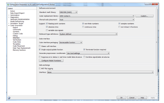
1. Under Simulation, click Model Configuration Parameters to open the dialog box.
2. Select the Code Generation category.
3. Set the System target file to ert.tlc, and select Generate code only.
4. Select Interface under the Code Generation category.
5. Set Code replacement library to ARM Cortex-A.
Task 3: Generate code
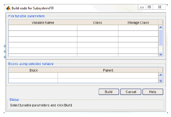
1. Right-click the FIR subsystem. From the drop-down menu that opens, choose C/C++ Code > Build This Subsystem. When the Build code for the Subsystem dialog box opens, click Build to start generating code.
2. When build finishes processing, a code generation report comes up.
3. Click on the FIR.c file. Notice the NE10 library function; ne10_fir_init_float in the initialize function (FIR initialize). Also, notice the NE10 function; ne10_fir_float_neon in the model step function (FIR step).
Task 4: Use Processor in the Loop (PIL)
To perform the previous steps using PIL, we need to have the Embedded Coder Support Package for ARM Cortex-A Processors, and the DST Support Package for ARM Cortex-A Processors.
The sample program, explains the process of inputting data from an Analog to Digital Converter, filter- it, output that to Digital to Analog Converter. This program for realizing the filter is developed using Micro-Modeler DSP and copied and brought into filter1.c/.h
#include "filter1.h"
const int inputBufferSize = 32; // duration of input
const int outputBufferSize = 32; // duration of output
void ADC1_read( short *pOutput, int nOutput ); // client generated task that inputs nOutput 16-bit signal from an ADC into buffer pOutput..
void DAC1_write( short *pInput, int nInput ); // Client generated task that outputs nInput 16-bit signal from buffer pInput to a DAC.
short inputBuffer[inputBufferSize], outputBuffer[outputBufferSize]; // assign an input and output buffer
int main( void )
{
int nProcessedSamples; // The count of samples output by the filter.
filter1Type *filter = filter1_create(); // produce an occurrence of the filter.
while( 1 ) // repeat,transmitting data from the ADC, to the filter, to the DAC
{
ADC1_read( inputBuffer, inputBufferSize ); // Read inputBuffer from the ADC (User-supplied)
nProcessedSamples = filter1_filterBlock( filter, inputBuffer, outputBuffer, inputBufferSize ); // Input from inputBuffer, filter the data ,output to outputBuffer
DAC1_write( outputBuffer, nOutputSamples ); // Write outputBuffer to the DAC
}
filter1_destroy( filter ); // demolish the filter (if we ever get here!)
return 0;
}
This sample explains the realization. The ADC and DAC expected to be interrupt-activated and double-buffered for better result. The time required for handling many samples simultaneously is minimum than one at a time, as those usually "batched" into a buffer of a few sample then handled in a cycle. Lengthier buffer gives better result, but increases the time taken.
Results and Discussion
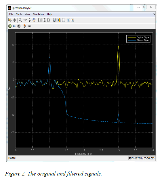
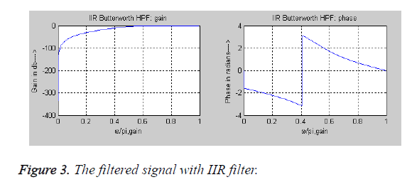
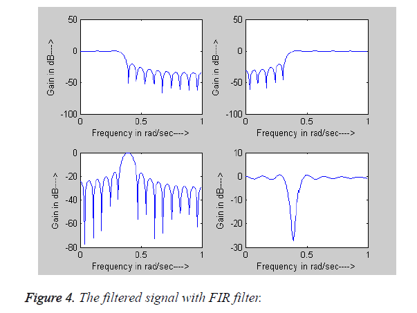
The outline arrived in this paper has been produced with ARM processor. For every order of the filter, the equivalent output document is generated for every achievable information circumstances and submitted the equivalent to MATLAB for simulations. This improved filter combined with sigma-Delta analog to digital converter having less delay of only 14.03 ns and consumes only 150 mw power. The result is shown in Figures 2-4.
The Table 1 shows the SNR before and after the planned method of filtering. The Table 2 shows the comparison performance in terms of delay between proposed and other similar existing methods [14]. As per this comparison modified booth with the Wallace tree method only has less delay compared with proposed method, but power consumption and complexity is more in Wallace tree method. The Table 3 shows the comparison of the hardware complexity among other digital filter implementation methods [15].
| Signal | Type of Noise | SNR Before Filtering | SNR After Filtering | SNR Improvement % |
|---|---|---|---|---|
| Record 1 | MA | 6 | 14.14 | 8.48 |
| Record2 | EM | 6 | 13.7 | 7.7 |
| Record3 | MA | 10 | 17.54 | 7.5 |
| Record4 | F/W | 11 | 18.54 | 8.5 |
Table 1. Test results to compare the SNR before and after the filtering.
| Methods | Delay ns. |
|---|---|
| Proposed | 10.2 |
| Modified Booth | 10.22 |
| Modified Booth with Wallace Tree | 8.9 |
| Distributed Arithmetic | 18.9 |
| Distributed Arithmetic with Partition | 16.804 |
Table 2. Delay Comparison of similar methods.
| Methods | No.of Multipliers | No.of adders | No.of Lookup Tables |
|---|---|---|---|
| Continuous Coefficient | 33 | 66 | 3207 |
| Max Precision method | 0 | 144 | 1152 |
| Hybrid ABC-GSA | 0 | 132 | 1056 |
| Hybrid ABC-HAS | 0 | 134 | 1072 |
Table 3. Hardware complexity comparison.
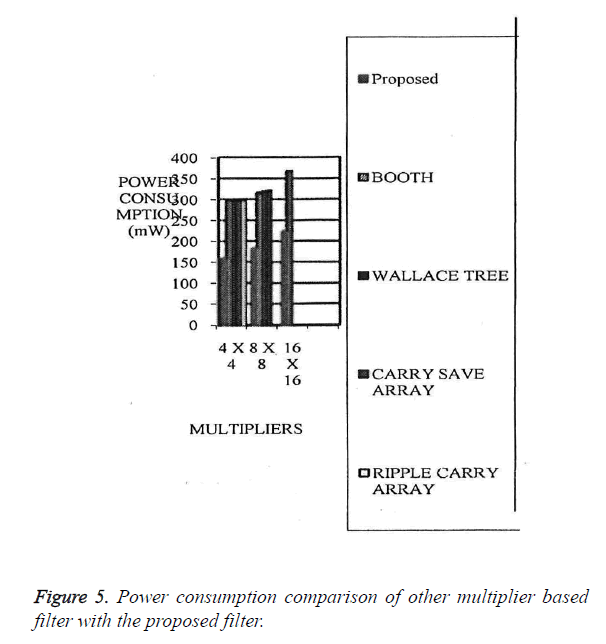
As per the above table the hardware complexity will be more for other similar digital filter implementation methods. The power consumption is an important phenomenon in performance comparison of digital filters. This comparison is given below in Figure 5.
If this proposed method is used in medical applications like filtering of ECG and other medical signals, due to the presence of ARM controller some other measurement, control, display and transmission of the signal to some other remote location also can be done without additional processor. The inputting and the handling of EMG signal are completed using the LPC-2103 microcontroller unit. The LPC- 2103 is 32-bit ARM-7TDMIS processing unit, using on-time emulation that associates the microcontroller unit with 32 KB implanted quick flash memory. Owing to unit's miniature dimension and little power utilization, the LPC -2103 is perfect in areas wherever dimension is main constraint.
STM32 as the major command chip, which has a plentiful task section and a superior customary communication interface can finish the acquirement, storage and signal communication of ECG signal exclusive of outer extension chip Therefore, the ECG apparatus has the characteristics of small volume, low power consumption which fulfill the basic necessities of the portable device. The trial results explain that the system has got the estimated effect.
The following features of ARM processor also can be utilized for supporting this signal processing implementation
• Piccolo DSP coprocessor.
• Various data memories for maximizing throughput
Conclusion
In this work, we projected and implemented a portable filter for real-time and personal purposes. We reduced the hardware complexity by using the digital filter-driven hardware architecture. According to the experimental results, the proposed filter has lower computational complexity than other existing filtering algorithms. The minimized number in hardware of this idea offers the benefit such as less consumption of space and power. The result shows that the revised filter has less delay and power. The power-delay product as well as the space-delay product of the planned outline shows a decrease in 16, 32, 64, 128-bit data. Also, it shows the success of this system and it is not the only exchange of delay for power and space. The revised style is with, less space, less power, uncomplicated and resourceful for ARM hardware realization.
References
- Chohan S, Kumar Y. Low power Designing of FIR Filters. Int J Adv Technol Eng Res 2012; 2: 59-67.
- Karunakaran S, Kasthuri N. Area and Power Efficient VLSIArchitecture for FIR Filter using Asynchronous Multiplier. Br J Sci 2011; 02: 61-68.
- Aktan M, Vurdakuland A, Dimdar G. An Algorithm for the Design of Low power Hardware Efficient FIR Filters. IEEE Transact Signal Process 2008.
- Mishra B, AI Hashimi BM. Subthreshold FIR Filter Architecture for Ultra Lowpowerapplication 2009; Springer PATM OS LNCS 5349.
- Zhao Q, Meng G. Design of Digital FIR Filters Using Differential Evolution Algorithm Based on Reserved Gene. Proceed IEEE Comput Soc Int Conf Informa Sci Manage Eng 2010.
- Lin MC, Chen HY, Jou SJ. Design Techniques for high speed multirate.multistage FIR digital filters. Taylor & Francis Int J Electronics 2006; 93: 699-701.
- Taylor G, Gallon I. A Mostly-Digital Variable-Rale Continuous-Time Delta-Sigma Modulator ADC. IEEE J Solid-State Circuits 2010; 45: 2.
- Blad A, Gustafsson O. Integer Linear programming Based Bil level optimization for High speed FIR Decimation Filter Architectures. Springer J Circuits Syst Signal Process 2010; 29: 8l-l01.
- Park SH, Kim PS, Kwon OK, Wook l-Iyun K. Estimation and detection of unknown inputs using optimal FIR filter. Elsevcir Automalica 2000; 36: 1481-1488.
- Vinod AP, Lai EMK. Low power and High-speed Implementation of FIR Filters For Software Defined Radio Receivers. IEEE Transact Wireless Commun 2010.
- Jijina GO, Ranganathan V. Design of a novel reconfigurable FIR filter by constant shin method based on 4-bit BCSE Technique. Int J Applied Eng Res 2014; 19: 13689-13697.
- Saravanan P, Latha B, Began BK. Comparative Study of Different Multipliers for Signalprocessing applications. Int J Appl Eng Res 2015; 10: 12-16.
- Liu J, Guo RX. Research and Design of Virtual FIR Digital Filter Based on LabVIEW. Appl Mech Material 2013; 244: 240-243.
- Golconda M, Somaiya KJ. Comparrative analysis of Multiplier and Multiplierless methods used to implement FIR Filter on FPGA. Int J Tech Res Appl 2016; 4: 370-375.
- Kalathi S. Efficient design of multiplier-less digital Channelizer using recombination non-uniform filter banks. J KSU Eng Sci 2015.
