ISSN: 0970-938X (Print) | 0976-1683 (Electronic)
Biomedical Research
An International Journal of Medical Sciences
Research Article - Biomedical Research (2017) Volume 28, Issue 6
Biomechanical analysis and comparison of actual lumbarbone with lumbar bone prototype
Navinkumar Krishnan*, MS Alphin and Roopan Doss TTB
Sri Sivasubramaniya Nadar College of Engineering, Chennai, Tamil Nadu, India
- *Corresponding Author:
- Navin Kumar Krishnan
Department of Mechanical Engineering
SSN College of Engineering, Chennai, India
Accepted on April 17, 2016
Biomechanics is of prime importance while designing any automobile, especially with the growing competition in that sector. Present day research focuses to a great extent on this aspect and especially on the comfort of the driver of the vehicle. Researches prove that there is increasing damage to the backbone of the person riding the automobile, due to ineffective design of the suspension system of the vehicle. Lumbar bone is that part of the backbone on which the entire mass of the body acts. Due to improper suspension system, the lumber bone gets extensively damaged, leading to severe health effects. Our thesis is to fabricate, analyse and compare the properties of a replica of human lumbar bone created from Acrylonitrile Butadiene Styrene (ABS) with that of an actual human lumbar bone. The MRI and CT scans of various bone samples are first collected. A prototype of the Lumbar bone is made for experimental studies. Then, the forces acting on a human bone during the actual conditions are considered and the prototype is tested for the same.
Keywords
Lumbar bone, Rapid prototyping, Stereolithography, Acrylonitrile butadiene styrene.
Introduction
Biomechanics is of prime importance while designing any automobile, especially with the growing competition in that sector. Present day research focuses to a great extent on this aspect and especially on the comfort of the driver of the vehicle.
Nowadays, most of the automobile riders are prone to an adverse phenomenon-“Back Pain”. Thereby, the riders are desperate to find a solution to the above mentioned problem. In our work, we created a prototype of the human lumbar bone using ABS, so that studies can be conducted upon models without the need for actual human bones.
Studies have shown that the part which is extensively affected is the Lumbar Bone. So, in order to move forward we developed a prototype of a human lumbar bone using Rapid prototyping (RPT). Mechanical tests were conducted on the prototype.
The regions of maximum distortion were identified from MRI scans of actual human lumbar bones and, then the forces acting on them were analyzed. These forces were applied on the prototype made out of ABS and their characteristics were compared.
Lumbar vertebrae
The Lumbar Vertebrae are the five vertebrae between the rib cage and the pelvis. The lumbar spine is designed to be incredibly strong, protecting the highly sensitive spinal cord and spinal nerve roots. At the same time, it is highly flexible, providing for mobility in many different planes including flexion, extension, side bending, and rotation. The lumbar bones are larger in size compared to other bones in the vertebral column. This accounts for the fact that the centre of mass of the human body acts predominantly on the lumbar vertebrae. The lumbar vertebrae are very important in supporting the upper body in an upright position and in permitting movement.
Forces acting on the lumbar spine
The loads acting on the spine can be classified into two major categories: (1) Physiological loads and (2) Traumatic loads.
The physiological loads can be further categorized into different classes with respect to the normal and common activities of the spine. They are long-term loads (in sitting, standing), short-term loads (in flexion, extension), dynamic loads (in running, jumping) and repeated or cyclic loads (in gait, walk). Traumatic loads are those that occur abruptly and unexpectedly with great magnitude (in impact, whiplash). All these loads have great impact on the lumbar spine. It is subjected to very high compressive load while lifting or holding weights, depending on the horizontal distance of the load from the lumbar spine. Vibrations from automobiles and cyclical loads cause a fair amount of tension on the lumbar bones resulting in structural changes and fatigue effects in the tissues of disks and vertebrae.
Experimentally, it has been found that the traumatic overload of the spine can damage the disk and facet joints. When a disc is loaded beyond its load-bearing capacity, structural damage may occur as a consequence of high-level short-term loads that exceed load tolerance. However, sub maximal long-term and repeated loads may also cause disc failure.
Methods
MRI scan image processing
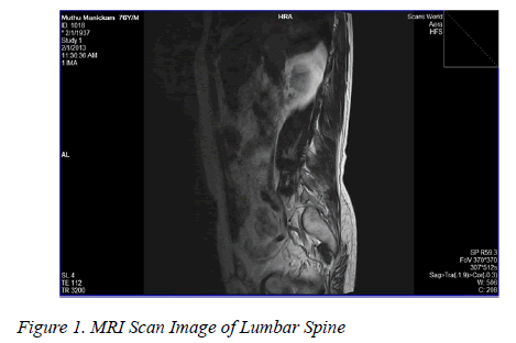
The MRI scan data was collected in DICOM format, as DICOM format is the most commonly used for image processing. The data availed from the MRI scan image is used to understand the impact of various loads acting on the lumbar bone. Data is extracted from the scan image and they are used for the reconstruction and analysis of the prototype.
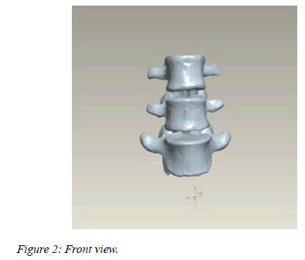
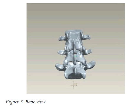
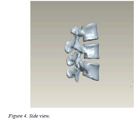
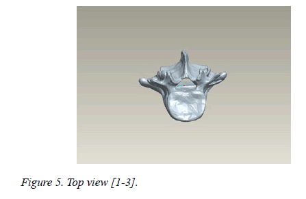
The region of study involved the MRI images obtained from that of a lumbar bone of a human. In all, 34 slice images were obtained each of 2 mm sliced segmentation for a height of 68 mm of the lumbar bone. In image processing, MRI images obtained are segmented and the region of interest (lumbar vertebrae) is extracted (Figures 1-5).
CAD modelling
In this step, data extracted from the MRI scan image is used to understand the structure of the lumbar bone. This is achieved by Stereolithography (STL) software. In Stereolithography, the surface of the image is broken into logical series of triangles. These images have an extension of (.stl). Each triangle is mentioned by its structure and its three vertices. The STL file format has become the Rapid Prototyping industry's de facto standard data transmission format, and is the format required to interact with Quickparts.
Rapid prototyping
Rapid prototyping is a group of techniques used to quickly fabricate a scale model of a physical part or assembly using three-dimensional computer aided design (CAD) data. Construction of the part or assembly is usually done using 3D printing technology.
In all commercial RP processes, the part is fabricated by deposition of layers contoured in a (x-y) plane two dimensionally. The third dimension (z) results from single layers being stacked up on top of each other, but not as a continuous z-coordinate. Therefore, the prototypes are very exact on the x-y plane but have stair-stepping effect in zdirection.
The material used for experimentation is Acrylonitrile Butadiene Styrene (ABS). Chemical formula (C8H8) x· (C4H6) y·(C3H3N)z) is a common thermoplastic [4-6].
Model reconstruction
At this point, the prototype is ready is for pre-construction. In order for the computer file to be constructed into an actual three-dimensional model, the file must be sliced into layers. Those layers will eventually be stacked on top of one another to create the final three-dimensional design. The sectioning of the file is done by another computer program designed specifically to perform that function. The lumbar bone prototype is formed by deposition of photosensitive polymer layer by layer inside contour of given lumbar bone profile. UV rays are made to fall on the photosensitive polymer which is moving along longitudinal axis of given lumbar bone profile. Due to sensitivity of the polymer it melts and gets deposited in one layer. Then it is allowed to cool for sometimes. The same process continues for every layer of prototype and formed.
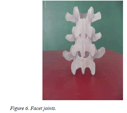
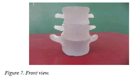
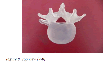
After the construction of prototype it is allowed to cure to get the definite shape of the lumbar bone. The supports which are given for the deposition of filling material are cleaned from the prototype profile. At this point, the prototype has been fully constructed. All that is left to get the prototype in "show" condition, which may include applying a sealant, painting, or adding other "finishing" touches to the lumbar bone prototype so that others can have an accurate depiction of what a fully functioning design would look like (Figures 6-8).
Results
Compressive testing
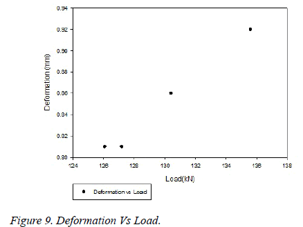
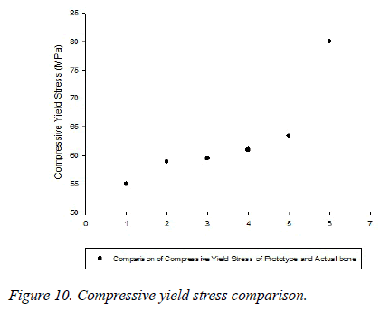
As compressive force mainly acts on the lumbar bone while riding in automobiles, Compressive tests were performed on the prototype model with the help of Universal Testing Machine. The specimen began to yield when a load of 135.6 kN was applied. The deformation at that point was 0.9 mm. This is in accordance with the graph provided herewith (Figures 9 and 10).
The load applied at yield point (P): 135.6 kN
The vertebrae transverse diameter (VTD): 52.2 mm of the L5 vertebra
The area of cross section of the bone (A) = π*VTD*VTD/4
(considering the surface to be circular)= π*52.2*52.2/4
=2138.9994 mm2
Therefore, the stress induced =Load Given/Area
= 135600/2138.9994
= 63.3941 N/mm2
= 63.3941 MPa
Young's modulus calculation
From the above calculations for stress induced it can be noted down as (σ) : 63.3941 MPa
The deformation was noted to be (δl): 0.9 mm
The body height of the bone (l): 30.7 mm
Young's Modulus (E)=σ*l/δl
=63.3941*30.7/0.9
=2115.433 Mpa
Tensile testing
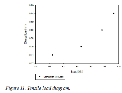
Similarly, tension tests were performed on the prototypes. The specimen began to yield for a load of 97.6 kN. The elongation was observed to be 0.8 mm (Figure 11).
The stress induced (σ)=Load/Area of cross section
=99300/ 2138.9994
=46.4237 MPa
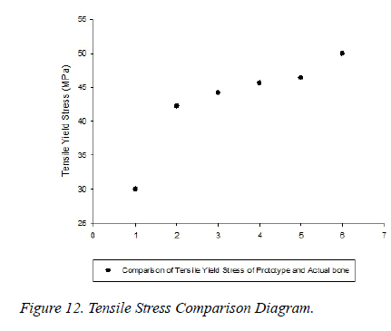
This is within the limits of tensile strength for ABS material as provided by reliable sources (41-60 MPa) (Figure 12).
Discussion
The compressive stress induced at yield point is 63.39 MPa. This value lies within the range stipulated for an ABS material which is 60-86 Mpa. The compressive stress range of actual human lumbar bone is within 55-80 MPa. This shows that the ABS material shows similar compressive characteristics as that of an actual human lumbar bone in the lower range of stress.
The Young’s modulus of the ABS material is in conformance with the original data.
The tensile strength is calculated to be 46.42 MPa. This calculated tensile strength is within the limits of tensile strength for ABS material as provided by reliable sources (41-60 MPa).
The limit for the tensile strength of an actual human lumbar bone has been stated to be within the range of 30-50 MPa. The calculated tensile strength for various specimens has been within this range and, hence the ABS material shows similar tensile characteristics with the stress in the upper region of the limits.
The material cannot be used for fracture testing because of the extended elongation of the material before fracture. Thus, it can be inferred from the research that Acrylonitrile Butadiene Styrene (ABS) can be used to test the tensile and compressive characteristics of human lumbar bone. They cannot be used for testing the fracture characteristics of the lumbar bone [10,11].
Author’s Contribution
All the authors have equally contributed to the study, research and the final draft of the report.
References
- Kurutz M. Finite Element Modeling of Human Lumbar Spine. Finite Element Analysis 2010.
- Jaiganesh V, Dhileep Kumar J, Girija Devi J. Replacement of Intervertebral disc in Spine by Poly(ethylene glycol) –diacrylate (PEGDA) material through Stereolithography. Biomedical Research 2015; 26: S22-25.
- Ferry PW, Feijen J, Grijpma M, Dirk WA. Review on stereolithography and its applications in biomedical engineering. Biomaterials 2010; 31: 6121-6130.
- Nilesh R, Gaikwad C. Rapid Prototyping by IOSR. Journal of Mechanical and Civil Engineering.
- Vila MM, Ginebra MP, Gil FJ, Planell JA. Effect of porosity and environment on the mechanical behavior of acrylic bone cement modified with acrylonitrile-butadiene-styrene particles: Part II. Fatigue crack propagation.Journal of Biomedical Materials Research 48: 128-134.
- Jacobs PF. Stereolithography and Other RP&M Technologies: From Rapid Prototyping to Rapid Tooling. 1996; 78-81.
- Cohen A, Mac DMD, Aviv A, Berman P, RizanNashef BA, JawadAbu-Tair DMD. Mandible reconstruction using stereo lithographic 3-dimensional printing modeling technology by Oral Surgery, Oral Medicine, Oral Pathology, Oral Radiology, and Endodontology. 2009; 108: 661-666.
- Jaiganesh V, Manivannan S, Maruthu B. Rapid Prototyping of Polymethyl Methacrylate as Replacement and Support of Spine in Human by Biomedical Research 2015; 26: S60-63.
- Borah B, Gross GJ, Dufresne TE, Smith TS, Cockman MD, Chmielewski PA, et al. Sod Three-Dimensional Microimaging (MRmI and mCT), Finite Element Modeling, and Rapid Prototyping Provide Unique Insights Into Bone Architecture in Osteoporosis. The Anatomical Record 2001; 265: 101-110.
- Beaupied H, Lespessailles E, Benhamou C. Elsevier MassonEvaluation of macro structural bone biomechanics by . Joint Bone Spine 2007; 74: 233e239.
- Boutroy S, Chapurlat R, Bouxsein ML. Determinants of the Mechanical Behavior of Human Lumbar Vertebrae after Simulated Mild Fracture. Journal of Bone And Mineral Research: The Official Journal Of The American Society For Bone And Mineral Research. 2011.
