ISSN: 0970-938X (Print) | 0976-1683 (Electronic)
Biomedical Research
An International Journal of Medical Sciences
Review Article - Biomedical Research (2015) Applications of Rapid Prototyping Techniques in Bio-Materials ARTBM2015
Construction of human knee bone joint model using FDM based 3D Printer from CT scan images.
1PhD Scholar, Department of Mechanical Engineering, Government College of Engineering, Salem, Tamilnadu, India
2Associate Professor, Department of Mechanical Engineering, Government College of Technology, Coimbatore, Tamilnadu, India
- *Corresponding Author:
- R. Malayalamurthi
Department of Mechanical Engineering
Government College of Technology
Coimbatore, Tamilnadu,India
Accepted July 07 2015
The purpose of this paper is to fabricate a model of human knee joint, bone whose raw image data’s were obtained from a computerized tomography machine using Stratasys “U Print SE Plus” 3D printer based on fused deposition modeling technique and validate the design by comparing the reproduced bone models with the original human knee joint bones and which will lead to detailed pre surgical studies and initiating step in implantation techniques. An integrated approach of imaging technology, segmentation using MIMICS software package and rapid prototyping technology was adopted in order to construct the human knee joint bones. Models of all the human knee joint bones- the femur, tibia, fibula and patella were constructed. The Patella bone in specific was constructed exactly as the same size of the original patella bone and was qualitatively validated by an expert anatomist and found to be satisfactory in design and the surface finish which may possibly be affected by mesh generation during a constructing phase in MIMICS software. As far as limitations are concerned, the femur, tibia and fibula bones exceeded the maximum dimensions of the “U Print SE Plus” 3D printer (203 x 203 x 152 mm). Followed by another limitation is that ABS plus – P430 and P400 thermoplastic are the only compatible material and other materials such as ABS-M30, PC-ABS, PC, Nylon 12 are not compatible with the machine. This paper deliberates a 3D visualization of the human knee bone model, particularly the patella which is constructed in its original size and was found to be validated. The present study enhances the versatility of fabricating bone models by RP for implantation as well for pre complex surgical studies.
Keywords
ABS thermoplastic, CT imaging technique, fused deposition modeling, MIMICS, rapid prototyping, 3D printer
Introduction
In this paper human knee joint bones are subjected to reconstruction through rapid prototyping technique 3D printer based fused deposition modeling technique. The human knee joint is a three dimensional complex structure whose details and feature cannot be easily represented by a solid model. Earlier models were axis symmetrically represented, but do not represent the three dimensional geometry of the knee bones accurately. Moreover, in the early stages the human knee joint bones were reproduced by milling machine by fixing certain tolerances in order to achieve the nearest representation of a bone model, but the quality of surface finish is not fair enough to be obtained and it involves an extensive process to achieve an appropriate model with good surface finishes. But now rapid prototyping has been developed as a breakthrough technology in the field of medical sector through which each and every part of not only the knee bone, but all other bones and dental parts can be reproduced accurately with the best features and anatomical data structures. The first section of the paper exhibits about the collection of CT image data from the CT scan machine in DICOM format. The second section comprises the sequential procedure of the conversion process of DICOM format into .stl format through a software package MIMICS version 16.0 and 3 matic version 8.0. The third section discusses about the importation of .stl files into the “U Print SE Plus” 3D printer via CatalystEX an interface used to feed the stl data into the 3D printer machine to generate prototype of each bone individually.
Finally the prototype bone models obtained are validated by comparing with original bone by an anatomy expert. The discussion is presented from the results obtained in the previous section.
Methodology
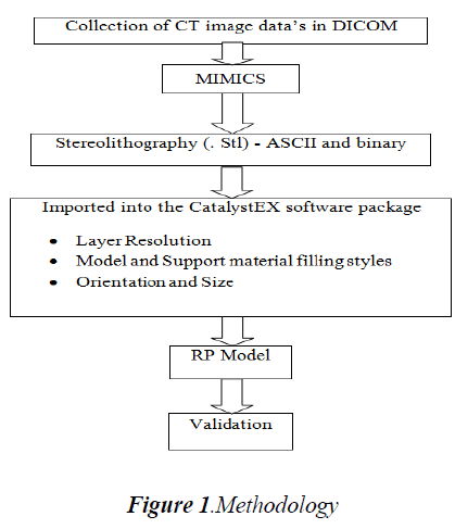
An integrated approach of CT Imaging technology, MIMICS and Rapid Prototyping Technology was adopted in order to obtain the bone models as accurate as of the original bones are present. The first step was involved in collecting and obtaining a CT scan data’s from a 128 CT slice machine. The data’s obtained for each part of the human knee joint bones were represented in the form of slices each of 1 mm layer thickness as two dimensional gray value images and were obtained in Digital Imaging and Communication in Medicine (DICOM) format. Since DICOM is a file format used in medical sector, it has to be converted in order to be compatible with the prevailing engineering software packages such as Solid works, ABAQUS and ANSYS. For this conversion, Materialise’s Interactive Medical Image Control System software (MIMICS) was used to convert the DICOM format files into the required STL file which is used for importing into CatalystEX, a software package that is integrated with the “U Print SE Plus” 3D printer for creating very accurate prototype of each bone individually. The reconstructed prototype bone is being validated by anatomical experts by comparing the reproduced bone obtained through the 3D printer with the original bone. The methodology flow is depicted below as shown in Fig.1.
CT images
The first step was performed by acquiring two dimensional sliced gray images from an untreated cadaver knee joint bone of approximately 35 years aged, Male, Right leg consisting of femur, tibia, fibula and patella. These knee bones were scanned using a CT scanner “SOMATOM Definition AS” (Siemens, Germany) with a slice thickness of 1 mm and were saved as DICOM format.
MIMICS
After obtaining the CT scan image data’s it is imported to the Materialise’s Interactive Medical Image Control System software (MIMICS) version 16.0, a software package that bridges medical and engineering file formats. The MIMICS version 16.0 software is an image – processing, interactive package tool with 3D visualization functions and segmentation of CT images and as well as 3D rendering of objects that interfaces between scanner data (CT, MRI), rapid prototyping , stl file format, CAD and finite element analysis. Additional module includes finite element meshes through which surface as well as volume mesh can be processed on the specified part model so as to create a smooth surface and volume respectively. The interface created to process the images provides several segmentation and visualization tools which are namely region growth, thresholding and wrapping technique.
Results and Discussion
CT images
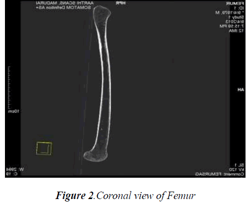
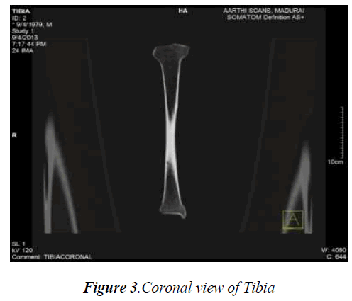
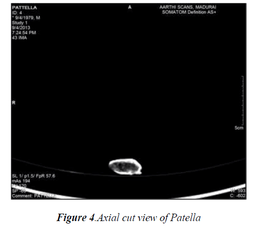
The number of CT images for the femur, tibia, fibula and patella bone obtained with a slice thickness of 1mm were found to be 427, 385, 381 and 85 respectively. These slices of images of each bone where imported together with the MIMICS 16.0 software package so as to obtain the whole structure of each bone which were further viewed as axial and coronal views in order to process the thresholding and other preprocessing methods. The various cross sectional CT images (axial, coronal) of each knee bone are represented in Fig.2, Fig.3 and Fig.4.
MIMICS
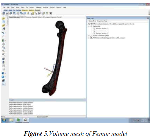
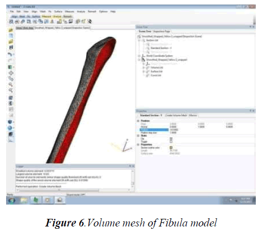
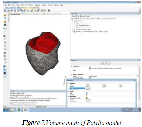
The tibia, femur, fibula and patella bone models were subjected to thresholding, region growth, wrapping technique and preprocessing method – volume mesh generation in order to obtain smoother and finer anatomical detail structure. Although each bone model were subjected to heavy mesh, in order to simplify the calculating process of each equivalent triangle consisting of faces, vertex and edges, reduced mesh is given through which acceptable smoother model is obtained. While calculating each mesh of each bone the inspection page of the 3matic 8.0 software displayed the histogram of bad triangles ranging from 2 to 10. Since each bone model consists of more number of triangles, minimal amount of bad triangles does not affect the anatomical structural details and hence the bad triangles having a range from 2 to 10 are considered to be a negligible amount. The cross section of each volume mesh of femur, fibula and patella is shown in Fig.5, Fig 6 and Fig 7.
3D Printer
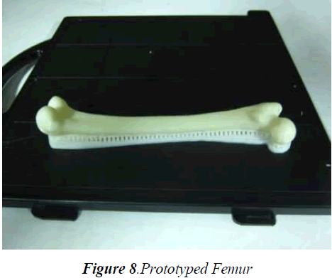
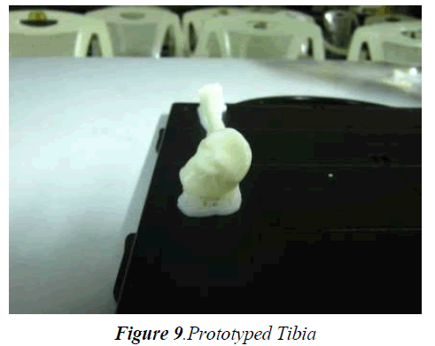
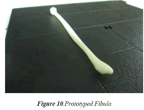
Material layer resolution of 0.254 mm thickness was adopted to reconstruct all bone models. The calculation performed by the Catalyst EX 4.4 software reveals that since femur is the largest bone, 14.24 cm3 of model material and 5.32 cm3 of support material were consumed. Fig.8 shows the reconstructed low density femur bone, which took 1 hour and 50 minutes by the 3D printer to complete the prototype model. The numbers of triangles used to create a smoother and finer model were represented as face count, vertex count and edge count and was found to be 102684 face counts, 51369 vertex counts and 154076 edge counts. The tibia bone prototype model consumed 10.00 cm3 of model material and 3.90 cm3 of support material to create a smoother and finer prototype tibia model in a span of 1 hour and 18 minutes, which are shown in Fig.9 with 27024 of face counts, 13514 of vertex counts and 40536 of edge counts. The fibula prototype model consumed 3.22 cm3 of model material and 1.98 cm3 of support material, to reconstruct the final prototype fibula model as shown in Fig.10 in a span of 33 minutes with 13632 of face counts, 6818 of vertex counts and 20448 as edge counts.
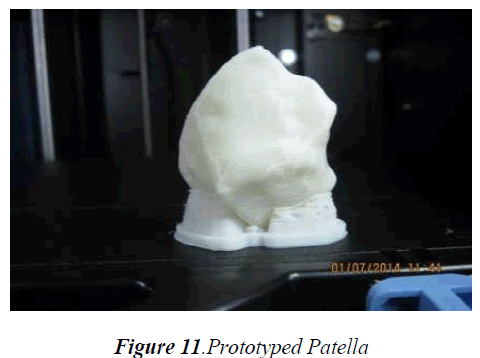
The patella bone representing just as the original size of the human patella consumed 5.95 cm3 of model and 1.35 cm3 of support material to reconstruct a smoother prototype model of the patella in 51 minutes whose number of face counts were 3768, vertex counts 1886 and edge counts 5652. A closer look of the prototype patella model as shown in Fig.11 reveals the layer thickness resolution, which represents a good surface finish with better anatomical details.
Validation
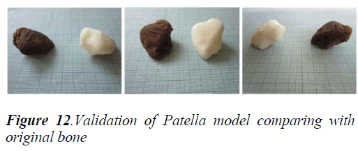
In order to ensure the accuracy of our model reconstruction, the bone models were validated qualitatively. Here the patella bone was considered to be validated since, only patella bone was able to be reconstructed to the original size of patella bone due to the limitations of the 3D printer. The results of the 3D printer as shown in figure 11 were compared with the original bone by an expert anatomist to determine if there is any missing or alteration in the anatomical structure of the original bone. The reconstructed prototype patella bone representing the original patella bone in terms of anatomical details and features was found to be satisfactory. The other bones femur, tibia, and fibula were also reconstructed but not to its original size since the limitations of 3D printer exists. Although the bones were reconstructed not to the original size, but the anatomical structural details and features were found to be unaltered and satisfactory. The comparison of the original patella bone with the prototype patella model is shown below in Fig.12.
Conclusion
This paper reports the RP model of each bone of the human knee joint were reproduced with“U Print SE Plus” 3D printer based on fused deposition modelling technique with a layer resolution thickness of 0.254mm and specifically the patella bone was validated and found that there was no significant alterations in the anatomical details. However the mesh generation in the modelling phase of the bone was reduced, which was even though at acceptable levels of anatomical details of each bone model obtained. Heavy volume mesh generations and surface mesh generation can be further implied in the model in order to obtain more realistic anatomical features through an RP model which can be suggested for implantation and for further deeper pre-complex surgical studies. The model obtained through 0.254 mm layer thickness has a better surface finish with good anatomical details when compared with the model obtained with a layer thickness of 0.3302 mm. The RP models were prototyped with model interior filling style selection as sparse low density. The other filling styles such as solid and sparse high density with layer thicknesses 0.254mm and 0.3302mm can be produced and subjected to comparison for achieving better details with good surface finished models.
Acknowledgment
The authors wish to gratefully acknowledge the TEQIP – II scheme of the World Bank for funding the “U Print SE Plus” 3D printer Rapid Prototyping Technology machine at the Government College of Engineering Salem – 636011, Tamilnadu, India.
References
- Tukuru N, Gowda KP, Syed Mansoor Ahmed, S Badami, “Rapid prototyping technique in medical field”. Research journal of pharmacy and technol- ogy 2008; 1(1): 341-344.
- Pero Raos, Antun Stoić, Mirjana Lucić, “Rapid prototyping and rapid machining of medical im- plants”. 4th DAAAM International Publications & Citing Data 2005; 1-8.
- Jelena Milovanović, Miroslav Trajanović, “Medical applications of rapid prototyping”, FACTA UNI-VERSITATIS, Series: Mechanical Engineering2007; 5(1): 79 – 85.
- Bal Sanghera, Satyajit naique,Yannis Papaharilaou, Andrews Amis, “Preliminary study of rapid proto- type medical models”, Rapid Prototyping Journal , Emerald Publications 2001; 7(5): 275-284.
- Ihab El-Katatny, S.H. Masood, Y.S. Morsi, “Error analysis of FDM Fabricated Medical Replicas” Rapid Prototyping Journal, Emerald Publi- cations 2010; 16(1): 36-43.
- Ratnadurai Dhakshyani, Yusoff Nukman, Abu Os- man Noor Azuan, “FDM models and FEA in dys- plastic hip”, Rapid Prototyping Journal, Emerald Publications 2012; 18(3): 215-221
