Keywords |
| Discrete Wavelet Transform (DWT), Stationary Wavelet Transform (SWT), Non Subsampled Contourlet Transform
(NSCT), Average, Choose max, Contrast, Gradient fusion Rules |
Introduction |
| Image fusion refers to the practice of amalgamating two
or more images into a composite image that assimilates
the information comprised within the individual image
without any artifacts or noise. Multi-modal medical image
fusion is an easy entrance for physicians to recognize the
lesion to analyze images of different modalities [1]. This
has been emerging as a new and talented area of research
due to the increasing demands in clinical applications. The
area of biomedical image processing is a rapidly rising area
of research from last two decades [2]. Medical imaging
is sub divided into functional and structural information
where magnetic resonance imaging (MRI) and computed
tomography (CT) afford high-resolution images by means
of structural and anatomical information whereas positron
emission tomography (PET) and single-photon emission
computed tomography (SPECT) images afford functional
information with low spatial resolution. Hence the goal is
to reckon the content at each pixel location in the input
images and preserve the information from that image
which best represents the true scene significant content or
enhances the effectiveness of the fused image for a precise application. |
| Here a novel method of six different fusion rules is used
for SWT, DWT and NSCT. These fusion rules are applied
for eight sets of PET, CT images. Choose max, average
fusion rules are applied for low frequency coefficients
and for high frequency coefficients choose max, gradient
and contrast fusion rules are applied and tested both
qualitatively and quantitatively. Section 2 briefly explains
related work, proposed methodology is given in Section
3, and fusion results are given in Section 4, quantitative
analysis of different fusion rules are given in section 5,
global comparison between different fusion rules are given
in section 6 and conclusion in Section 7. |
Related Work |
| Rajiv Singh, Ashish Khare et al., proposed complex
wavelet transform which fuses coefficient of input source
images using maximum selection rule [3] .These results
are compared with LWT, MWT, SWT and also with CT,
NSCT, DTCWT and PCA methods. For fusion of images
maximum selection rule is applied from level 2 to 8 for three
different sets of multimodal medical images. Further it is concluded that the results obtained proves that the quality
of fused image increases, as the level increases. Andreas
Ellmauthaler et al., proposed a fusion scheme based on
Undecimated wavelet transform [4]. This splits the image
decomposition procedure into two sequential filtering
operations by spectral factorization of analysis filters.
Here fusion takes place subsequent to convolution with
the first filter pair. Best results are obtained by applying
UWT calculation of low-frequency coefficients and the
outcome are compared with wavelets [5]. The coefficients
of two different types of images through beyond wavelet
transform are obtained and then the low-frequency and
high frequency coefficients are selected by maximum
local energy and sum modified Laplacian method.
Ultimately, the output image is procured by performing
an inverse beyond wavelet transform. The results show
that the maximum local energy is a new approach for
obtaining image fusion with adequate performance. Yi Li,
Guanzhong Liu proposed cooperative fusion mode, where
it is considered the activity levels of SWT and NSCT at the
same time [6]. Initially, every source image is decomposed
by SWT and NSCT. Later fused coefficients are attained
by combining the NSCT coefficients, by taking into
account both the SWT coefficients and NSCT coefficients.
Manoj D. Chaudhary, Abhay B. Upadhyay et al., proposed
a method where the images are extracted using SWT
initially and then global textural features are extracted by
gray level co-occurrence matrix [7]. Different DWT, SWT
based image fusion methods are discussed in [8-14]. |
Proposed Methodology |
| As fusion rules play a significant role in image fusion,
to fuse images after decomposition average, choose
max rules are applied for low frequency and for high
frequencies contrast, gradient and choose max rules are
utilized for DWT /SWT/NSCT. The simple block diagram
representation is specified below in Figure 1. |
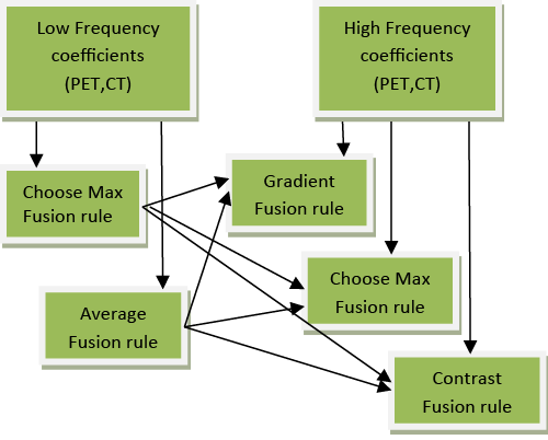 |
| Figure 1: Different fusion rules |
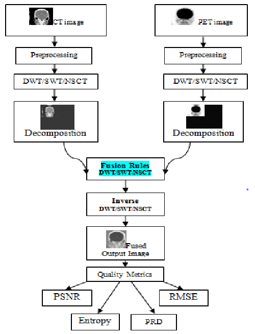 |
| Figure 2: Proposed image fusion algorithm |
| The block diagram illustration of the proposed algorithm is specified below in Figure 2. The initial step is to acquire
PET and CT images as input. In image preprocessing after
retrieving the input images, to speed up execution time,
image resizing is performed followed by RGB to gray
conversion. |
| Next step is to decompose the images into LL, LH, HL and
HH frequency coefficients using DWT/SWT/NSCT. For
low frequency coefficients choose max, average rules are
applied whereas choose max, gradient and contrast fusion
rules are used for high frequency coefficients. Different
fusion rules are implemented for DWT/SWT/NSCT.
To reconstruct the original images inverse transform is
applied and to validate the results different performance
metrics are used. |
Discrete wavelet transform (DWT) |
| The discrete wavelet transform (DWT) is a direct
transformation that works on an information vector whose
length is a whole number power of two, changing it into a
numerically diverse vector of the same length. This isolates
information into distinctive frequency components, and
studies every segment with resolution coordinated to its
scale [15]. DWT of an image delivers a non-redundant
image representation, which gives better spatial and
spectral localization compared to existing multiscale
representations. It is computed with a cascade of filters
followed by a factor 2 sub sampling and the principle
highlight of DWT is multi scale representation. By
utilizing the wavelets, given functions can be analyzed at
different levels of resolution. DWT decomposition utilizes a course of low pass and high-pass channels and a subsampling
operation. The yields from 2D-DWT are four
images having size equal to half the size of input image.
So from first input image HHa, HLa, LHa, LLa images
are obtained and from second input image HHb, HLb,
LHb, LLb images are obtained. Here LL image contains
the approximation coefficients. LH image contains the
horizontal detail coefficients. HL image contains the
vertical detail coefficients and HH contains the diagonal
detail coefficients. One of the significant disadvantages of
wavelet transform is their absence of translation invariance
[16]. |
Stationary wavelet transform (SWT) |
| The stationary wavelet transform (SWT) is an expansion
of standard discrete wavelet transform (DWT) that utilizes
high and low pass channels. SWT apply high and low pass
channels to the information at every level and at next stage
it produces two sequences. The two new successions will
have same length as that of first grouping. In SWT, rather
than annihilation the channels at every level is altered by
cushioning them with zeroes. Stationary Wavelet Transform
is computationally more complex. The Discrete Wavelet
Transform is a time variant transform. The best approach
to restore the interpretation invariance is to average some
slightly distinctive DWT, called undecimated DWT to
characterize the stationary wavelet transform (SWT)
[17]. SWT does this by suppressing the down-sampling
step of the DWT and instead up-sampling the filters by
padding with zeros between the filter coefficients. After
decomposition, four images are generally furnished (one
approximation and three detail coefficients) which are at
half the resolution of the original image in DWT, whereas
in SWT the approximation and detail coefficients will have
the same size as the input images. SWT is like discrete
wavelet transform (DWT), however the main procedure of
down-sampling is stifled which implies that SWT is shift
invariant. It applies the DWT and excludes both downsampling
in the forward and up-sampling in the reverse
direction. More precisely, it executes the transform at each
point of the image and saves the detail coefficients and
uses the low frequency information at each level. |
Non subsampled contourlet transform (NSCT) |
| Wavelet transform has been considered as a ideal strategy
for image fusion [18]. Despite the fact that DWT is most
normally used, it suffers from shift variance issue. To
overcome the above issue SWT was proposed. Although
SWT is shift invariant technique, it performs better at
segregated discontinuities, yet not at edges and textured
locals. To conquer the above drawbacks and to hold the
directional and multi scale properties of the transform
non subsampled contourlet transform (NSCT) has been
proposed which decomposes the images in the form of
contour segments. Therefore, it can capture geometrical
structure of an image in a more efficient manner than
existing wavelet techniques. NSCT is an amalgamation of both non subsampled pyramid and non-subsampled
directional filter bank. Also this is a geometric evaluation
technique that utilizes the geometric regularity which is
present in the individual input images and furnishes an
output image with better localization, multi-direction and
shift invariance. |
Fusion Rules |
| Selection of fusion rules plays a significant role in
image fusion. Most information of the source images is
kept in the low-frequency band as it is a smoothed and
subsampled version of original input image [19]. Higher
value of wavelet coefficients carries salient information
about images such as corners, edges and hence maximum
selection rule, gradient and contrast fusion rule has been
chosen for fusion [20]. |
Maximum or choose max fusion rule |
| Higher value of wavelet coefficients contains most
important information about images such as edges, and
corners [3]. Therefore, in maximum selection rule for
fusion, smaller magnitude complex wavelet coefficients
are replaced by means of higher magnitude complex
wavelet coefficients. For every corresponding pixel in
input images, the pixel with the maximum intensity is
chosen and used as the resultant pixel of the fused image.
The major steps of the proposed algorithm are summarized
as follows: |
| If, |
| LL1(i,j) > LL2(i,j) |
| Lout(i,j) = LL1(i,j); |
| else |
| Lout(i,j) = LL2(i,j); |
| Where, LL=indicates low frequency coefficients,
Lout=indicates output image value, LL1=indicates
coefficients of CT image and LL2=indicates coefficients
of PET image. |
Average fusion rule |
| This method is a simple one where fusion is achieved by
calculating average of corresponding pixel in each input
image. |
| Low frequency components are fused by averaging
method. |
| Mean = (LL Part of PET Image + LL Part of CT Image)/2. |
Gradient rule |
| The term image gradient is a directional change in the
intensity or color of an image that may be used to extract
information. This considerably reduces the amount of
distortion artifacts and contrast information loss that is
observed in fused output images obtained from general
multiresolution fusion schemes [21]. This is because;
fusion in the gradient map domain considerably improves the reliability of information fusion processes and the
feature selection. Gradient represents the steepness and
direction of that slope. The appropriate high frequency sub
bands are chosen (LH, HL and HL) to find out the gradient
value. These values of two input images are compared and
the better values are taken as the output and given by, |
| dx = 1; |
| dy = 1; |
| [dzdx1,dzdy1] = gradient (LH1,dx,dy); |
| gm1 = sqrt ((dzdx1 .^ 2 + dzdy1 .^2)); |
| where, |
| dx- Slope along horizontal direction. |
| dy- Slope along vertical direction. |
| dz- Slope along diagonal direction. |
Contrast rule |
| Contrast measures the difference of the intensity value at
some pixel from the neighboring pixels as human visual
system is very sensitive to the intensity contrast rather
than the intensity value itself. Initially the mean value for
low frequency part is calculated. Then maximum values
for the LL, HL, LH and HH part are calculated. |
| Contrast value = Mean/Maximum value of the visible sub
band |
| Contrast values of two input images are compared and
then mean and maximum of the respective sub bands are
calculated as below, |
| AL_M = mean (mean (LL1 (i-1:i+1,j-1:j+1))); |
| AL_M = mean (mean (LL1 (i-1:i+1,j-1:j+1))); |
| AL_H = max (max (LH1(i-1:i+1,j-1:j+1))); |
| AL_V = max (max (HL1(i-1:i+1,j-1:j+1))); |
| AL_D = max (max (HH1(i-1:i+1,j-1:j+1))); |
| Con_A_H (i-1,j-1) = AL_H/AL_M; |
| Con_A_V (i-1,j-1) = AL_V/AL_M; |
| Con_A_D (i-1,j-1) = AL_D/AL_M; |
Results and Discussion |
| It is essential to assess the fusion action from both subjective
and objective image quality feature measurement. Here
the performance of the proposed work is compared with
eight sets of real time medical images obtained from
Bharat Scans. For DWT, SWT and NSCT six sets of
fusion rules are applied for eight sets of PET, CT medical
images. For the fusion of low frequency coefficients
choose max and average fusion rules are applied whereas
choose max, gradient and contrast fusion rules are used
for high frequency coefficients. The numerical values for
the qualitative measurements are given below followed by
quantitative analysis. In Figure 3, column A1 represents Computed Tomography (CT) and A2 represents Positron
Emission Tomography (PET) images. The results of the
corresponding outputs of CT, PET images are given as
output images from A3-A20------ H3-H20. In this, Avg.
indicates average, Con. denotes contrast, Gra. denotes
gradient and Max. denotes choose max fusion rule. Figure
4 |
Global Comparison |
| Quality assessment of the fused image is complicated in
general, as the ideal fused image is often associated by
specific tasks. Also subjective methods are complicated
to perform as they are based on psycho-visual testing.
These are also expensive in terms of time and equipment
required. Furthermore, there is slight difference between
fusion results and hence subjective means are difficult
to evaluate the correct fusion results. A lot of objective
evaluation methods have been developed for these reasons
and four of them are given below. |
Peak signal to noise ratio (PSNR) |
| As higher values of PSNR gives better results, for DWT and
SWT the average, gradient fusion rule gives good results
for all eight image sets. On comparing PSNR values of
NSCT with different fusion rules average, gradient fusion
rule gives better results for image sets 2, 3, 4, 5, 6, 7 and
8 while maximum, gradient fusion rule gives better result
for image set 1. |
Root mean square error (RMSE) |
| On comparing RMSE values of DWT with different fusion
rules average, gradient fusion rule gives better results for
image sets 2, 3, 4, 5, 7 and 8. Maximum, contrast fusion
rule gives better result for image set 1while average,
maximum fusion rule gives better result for image set
6. For SWT with different fusion rules average, gradient
fusion rule gives better results for all image sets. On the
other hand for NSCT average, gradient fusion rule gives
better results for image sets 2, 3, 4, 5, 6, 7 and 8 while
maximum, contrast rule gives better result for image set 1
as lower values of RMSE gives better results. |
Entropy |
| Entropy of an image designates the information content
of the merged image and hence its value must be high. On
comparing entropy values of DWT with different fusion
rules average, gradient fusion rule gives better results for
image sets 1,2,4,5,6,7 and 8 while maximum, contrast
fusion rule gives better result for image set 3. For SWT with
different fusion rules average, gradient fusion rule gives
better results for images 1, 2, 3, 4, 5,6and 8 and average,
maximum fusion rule gives better result for image set 7.
On comparing entropy values of NSCT average, gradient
fusion rule gives better results for images 2, 3, 4, 5, 6, 7
and 8 and average, contrast fusion rule gives better result
for image set 1. |
Percentage Residual Difference (PRD) |
| While comparing PRD values of DWT with different
fusion rules average, gradient fusion rule gives better
results for all image sets. On comparing PRD values of
SWT average, gradient fusion rule gives better results for
images 1,2,3,4,5,6 and 8 and average, contrast fusion rule
gives better results for image set 7 . For NSCT average,
gradient fusion rule gives better results for image sets 2, 3,
4, 5, 6,7 and 8 while maximum, contrast fusion rule gives
better result for image set 1. |
 |
| Figure 3: Results for different fusion rules |
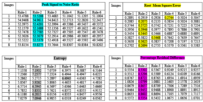 |
| Figure 4A: Quantitative analysis of Discrete Wavelet Transform (DWT) |
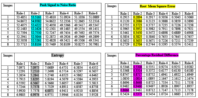 |
| Figure 4B: Quantitative analysis of Stationary Wavelet Transform (SWT) |
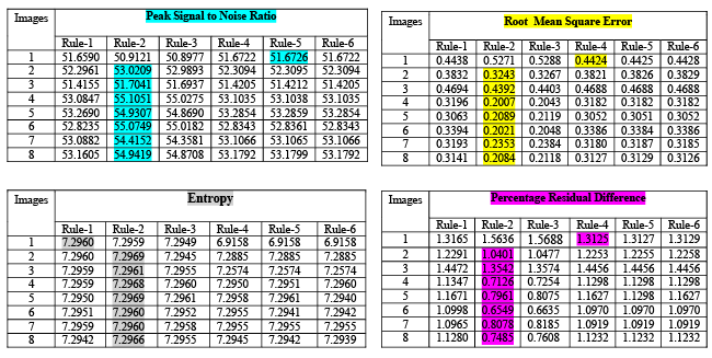 |
| Figure 4C: Quantitative analysis of Non Subsampled Contourlet Transform (NSCT) |
Conclusion |
| A novel pixel based image fusion method using using
six different fusion rules are proposed in this paper
and the results are emphasized in section 4 for discrete
wavelet transform, stationary wavelet transform and non
subsampled contourlet transform. From the observation
of the results it is clear that average fusion rule for low
frequency coefficient and gradient fusion rule for high
frequency coefficient provides better results than other
fusion rules for all discrete wavelet transform (DWT),
stationary wavelet transform (SWT) and Non subsampled
contourlet transform (NSCT). Pixel level fusion is suffered
by blurring effect that directly affects the contrast of the
image in maximum selection rule, compared to average
fusion rule. Hence for low frequency coefficients average
fusion rule is more suitable than the other. Gradient fusion
considerably minimizes the loss of contrast information
and amount of distortion artifacts in fused images. Also this
is because fusion in the gradient map domain significantly
improves reliability of information fusion processes and
the feature selection. Hence for high frequency gradient
based fusion rule is more suitable than other two. Also the
time taken for the execution of SWT is more than DWT
and NSCT. Hence from the observation it is concluded
that average and gradient based fusion rules works better
for bio medical images than other fusion rules. |
References |
- Wang L, Li B, Tian LF. Multi-modal medical image fusion using the inter-scale and intra-scale dependencies between image shift-invariant shearlet coefficients 2014; 19: 20-28.
- Daneshvar S,Ghassemian H. MRI and PET image fusion by combining IHS and retina-inspired models 2010; 11: 114-123.
- Singh R, Khare A. Fusion of multimodal medical images using Daubechies complex wavelet transform ? A multiresolution approach 2014; 19: 49-60.
- Ellmauthaler A, Carla L. Pagliari , Da Silva AB. Multiscale Image Fusion Using the Undecimated Wavelet Transform With Spectral Factorization andNonorthogonal Filter Banks. IEEE Transactions on image processing 2013;22: 1005-1017.
- Huimin Lu, Lifeng Zhang, Seiichi Serikawa. Maximum local energy: An effective approach for multisensor image fusion in beyond wavelet transform domain 2012; 64: 996-1003.
- Yi Li, Guanzhong Liu. Cooperative Fusion of Stationary Wavelet Transform and Non-subsampled Contourlet for Multifocus Images 2009;1: 314-317.
- Chaudhary MD, Upadhyay AB. Fusion of local and global features using Stationary Wavelet Transform for EfficientContent BaseImage Retrieval 2014; 1-6.
- Huang PW, Chen CI, Li PL. PET and MRI Brain Image Fusion Using Wavelet Transform with Structural Information Adjustment and Spectral Information Patching. 2014; 1-4.
- Sahoo T, Patnaik S. Cloud Removal from Satellite Images using Auto Associative Neural Network and StationaryWavelet Transform2008; 100-105.
- Shi H, Fang M. Multi-focus Color Image Fusion Based on SWT and HIS. 2007; 461-465.
- Chabira B, Skanderi T, AichoucheBelhadjaissa. Unsupervised Change Detection from Multi temporal Multichannel SAR Images based on Stationary Wavelet Transform 2013; 1-4.
- Zhang X,Zheng Y, Peng Y. Research on Multi-Mode Medical Image Fusion Algorithm Based on Wavelet Transform and the Edge Characteristics of Images 2009; 1-4.
- Nunez J, Otazu X, Fors O, Prades A. Multiresolution-Based Image Fusion with Additive Wavelet Decomposition. IEEE Transactions on Geoscience and remote sensing 1999; 37: 1204-1211.
- Kok C, Hui Y, Nguyen T. Medical images pseudo coloring by wavelet fusion. Bridging disciplines for biomedicine. Proceedings of 18th Annual International Conference of the IEEE 1996; 2: 648-649.
- Kannan K, Perumal SA, Arulmozhi S. Optimal Decomposition Level of Discrete, Stationary and Dual Tree Complex Wavelet Transform for Pixel based Fusion of Multi-focused Images. Serbian Journal of Electrical Engineering2010; 7: 81-93.
- Simoncelli EP, Freeman WT,Adelson EH, Heeger DJ. Shiftable MultiscaleTransforms. IEEETransactionsonInformation Theory 1992; 38.
- Pesquet JC, Krim H, Carfatan H.Time-invariant orthonormal wavelet representations. IEEE Trans on Signal Processing1996; 44.
- Bhatnagar G, WuJQ, Zheng Liu Z. Directive contrast based multimodal dical image fusion in NSCT domain. IEEE Transactina2013; 15: 1014-1024.
- Yang Y, Park DS, Huang S, Rao N. Medical Image Fusion via an Effective Wavelet-Based Approach. Journal on Advances in Signal Processing 2010.
- IndiraKP ,Rani Hemamalini R. Impact of co-efficient selection rules on the performance of DWT based fusion on medical images2015; 1-8.
- Petrovic VS,XydeasCS.Gradient-based multiresolutionimage fusion 2004; 13: 228-237.
|


